


How to Size a Steam Heat Exchanger Correctly
A steam heat exchanger has one job: take heat from steam and put it into something else — water, oil, air or a process fluid — without the two streams ever mixing. Get the sizing right and it holds temperature steadily, drains cleanly and lasts for years. Get it wrong and you end up with the opposite of what you paid for: a unit that can’t reach temperature at full load, or one that hunts, waterlogs and hammers at low load.
Sizing isn’t guesswork, but it isn’t quite as simple as picking a unit off a chart either. This is a practical walk-through of what actually drives the size of a steam heat exchanger, the steam-specific traps that catch people out, and why measuring your real duty matters more than any rule of thumb.
Start with the duty, not the equipment
The first number you need is the heat duty — how much energy you have to move, usually expressed in kilowatts. For a fluid being heated, it comes from three things: how much of it you’re heating, its specific heat, and how far you’re raising its temperature.
Q = ṁ × cp × ΔT
In plain terms: flow rate × the fluid’s heat capacity × the temperature rise. Heat 16,000 litres an hour of water from 15 °C to 80 °C and the duty is fixed by physics — no exchanger changes it. That duty is the target the heat exchanger has to hit, so it’s worth getting from real measured flows and temperatures rather than nameplate assumptions.
Then size the surface area
Once you know the duty, the exchanger’s job is to transfer it across a surface. Three things set how much surface area you need:
A = Q ÷ ( U × LMTD )
- U — the overall heat transfer coefficient. How readily heat moves from the steam, through the tube or plate wall, into the process fluid. It depends on the materials, the geometry and how clean the surfaces stay.
- LMTD — the log mean temperature difference. The effective temperature gap driving heat across the wall, averaged along the exchanger. A bigger gap moves more heat per square metre, so a higher steam temperature lets you use less area.
- A — the surface area. The answer you’re solving for: the size of the unit.
The diagram below shows how these pieces fit together on a shell-and-tube unit.
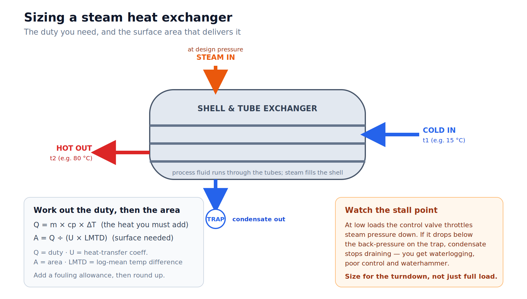
Sizing a steam heat exchanger: the duty you need, the surface area that delivers it, and the stall point to design around.
The takeaway is that area isn’t chosen directly — it falls out of the duty you need and the conditions you’re running. Push the steam pressure up and you raise the temperature difference, shrinking the unit. Drop it and you need more surface to do the same job.
Don’t size for full load alone — watch the stall point
This is the mistake that separates a steam heat exchanger from a plain water-to-water one. Steam-heated exchangers are usually controlled by throttling the steam supply to hold an outlet temperature. At part load, that control valve closes in, and the steam pressure inside the shell falls.
Push it far enough and you hit the stall point: the steam pressure drops below the back-pressure the condensate has to overcome to drain. Condensate stops leaving, the exchanger floods, and you get unstable control, corrosion and waterhammer — the bangs and shudders that crack fittings and shorten the life of the unit.
Avoiding stall is a design decision, not an afterthought. It usually means selecting the right condensate drainage — a correctly sized trap, or a pump-trap where the unit can go into a vacuum — and choosing a control and valving arrangement that keeps condensate moving across the whole load range. A unit sized only for its full-load duty can still fail at the low loads it spends most of its life at.
The inputs to nail down before sizing
Pulling it together, a sound sizing exercise needs:
- The real duty — measured flows and inlet/outlet temperatures, not assumed ones.
- Available steam pressure at the exchanger, which sets the temperature you have to work with.
- The turndown range — the lowest load the unit must control at without stalling, not just the peak.
- A fouling allowance — extra area to keep performance up as surfaces scale or foul over time.
- Materials suited to the fluids, so corrosion doesn’t quietly erode U and shorten life.
Skip any of these and the unit is sized for a plant that doesn’t exist. The most common result is an exchanger that looks fine on paper but can’t hold temperature on a cold start or chatters its way through every quiet shift.
Plate or shell-and-tube?
Both are common in industrial heat exchangers, and the choice affects the sizing. Plate units pack a lot of surface into a compact, efficient package and suit close temperature approaches; shell-and-tube units are robust, tolerate higher pressures and fouling, and are easy to clean and re-tube. Which one wins depends on your fluids, your space, your maintenance preferences and how aggressively the process fouls — another reason the duty and conditions need to be pinned down before the format is chosen.
Get the duty measured, then size with confidence
A correctly sized steam heat exchanger is the product of a few honest numbers: the real duty, the real steam pressure, and the real load range it has to cover. The equations are straightforward; the discipline is in feeding them measured data rather than assumptions.
That’s where a system appraisal earns its place. Proper steam and water metering gives you the flows and temperatures the sizing depends on, and a consultancy and system design review turns them into a specified unit — sized for your turndown, drained against stall, and built into a packaged heat exchanger solution ready to install. It can then be delivered and installed as a single turnkey scope.
If you’re specifying a new exchanger or troubleshooting one that won’t hold temperature, get in touch with Energy Specialties and we’ll help you size it on real numbers.